
Informative article
Hybrid injection moulding: plastic and metal in a single component
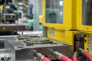
Hybrid injection moulding combines the dimensional accuracy and strength of metal inserts with the design flexibility and weight advantages of plastic: all in a single process step.
What is hybrid injection moulding and how does it work?
In hybrid injection moulding, metal components—such as inserts, bushings, wires or stamped parts—are placed into the mould as inserts and then overmoulded with plastic. The result is a functionally integrated component in which metal and plastic are inextricably bonded. The metal insert provides load-bearing capacity, a precision connection or electrical conductivity, whilst the plastic shell adds structural integrity, insulation or aesthetic appeal. Vertical injection moulding machines, in which the mould opens vertically, are particularly well-suited to this process, as gravity helps to hold the insert in position whilst the mould is closing.
Applications: where does hybrid injection moulding offer added value?
The added value of hybrid injection moulding is greatest where the properties of plastic alone are insufficient, but using solid metal would be too heavy, too expensive or too complex. Typical applications include screw connections in plastic housings, where a metal threaded insert prevents wear during repeated assembly and disassembly, and electrical connector housings where conductive pins must be positioned with precision. In the automotive sector, hybrid components are used, for example, in mounting brackets that combine weight reduction with mechanical robustness.
Threaded inserts in technical enclosures and machine components
Guide pins and contacts in electrical connectors
Overmoulding of stamped parts and sheet metal for structural bracket applications
Cable glands and seals around metal pipes or rods
Dimensional accuracy and positioning of the insert
The positional accuracy of the metal insert in the final product is determined by the precision with which the insert is positioned and secured in the mould. Minor deviations in insert position can lead to uneven wall thicknesses around the insert, internal stresses or even cracks during cooling. The mould design must provide reliable fixing points for the insert, preferably via interference fits or magnetic holders. For high-volume production, automated insert placement using a robot is essential to control cycle time and eliminate human placement errors.
Stress during cooling: a critical design consideration
Metal and plastic have very different coefficients of thermal expansion. As the part cools after injection moulding, the plastic shrinks considerably more than the metal, which builds up internal stresses around the insert. If the transition is poorly designed – for example, if the wall thickness around the insert is too thin or there are abrupt geometric transitions – these stresses can lead to cracking or deformation. Moldflow simulation is a valuable tool for visualising the stress distribution as early as the design phase.

Moulding challenges into Reality
